ESP8266 Http Server
The ESP 8266 is the goto chip when developing IoT networks. It has:
- 1MB Flash storage (earlier blue models have half)
- Built-in TCP/IP stack (of course!!!)
- Supports 802.11 b/g/n protocol
- Has 2 pins for general purposes.
This module is pre flashed with a software communicating with so called AT commands. It’s a bit limited in the use cases I’m aiming for so we need to flash our own software using the arduino platform. This will enable us to use 2-wire communication using I2C for connection with multiple peripherals.
Documentation for the ESP8266 chip
I purchased my boards on ElectroKit. My favorite shop for electronics in sweden.
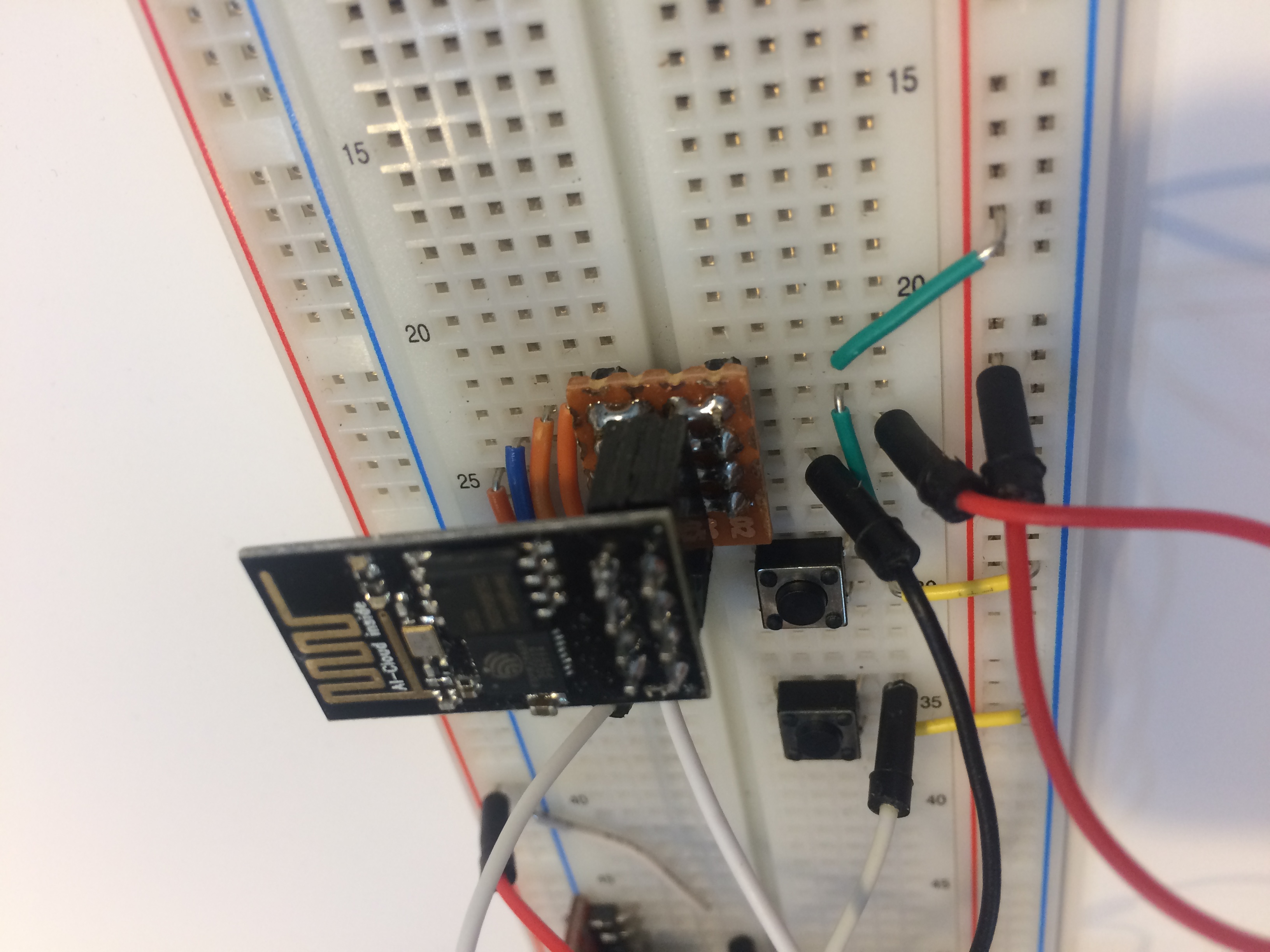
The first issue with the ESP 8266-01 is the pins location. The footprint (2x4 row) is small but not very breadboard friendly. An adapter was created for flashing/prototyping.
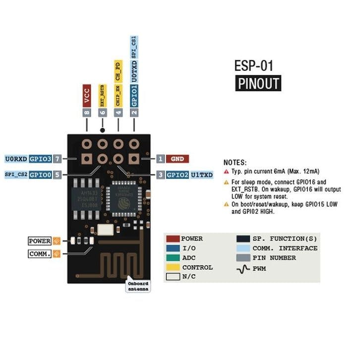
Back to pinout configuration. Above is a image of the available pins on the ESP 8266-01.
ESP8266 runs on 3.3V for both Vin and GPIOs!!!
To flash the ESP you would need a USB to Serial converter. These can be bought seperatly like the one on the image further down or you could use any arduino compatible board that has a USB port available. My adapter is a FTDI232 that allows us to switch between 3.3V and 5V for signal, I only have to move a jumper to select the correct level. This is required for communicating with our ESP. When you are using a Arduino to flash, it probably runs on 5V, then you need a voltage divider for the RX line (input signal for the ESP). I’ve accidentally burned 2 of these chips this way.
This is how it ended up:
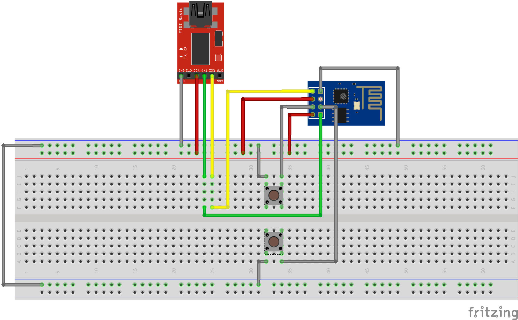
The buttons are used to get the chip into “flash mode”. The documentation describes that GPIO 0 should be low on reboot, so by pressing both buttons at once and then releasing the reset button after a second or two the chip should be in a good mood to receive new instructions.
When everything’s hooked up correctly it’s time for the code part. Start the Arduino IDE and install additional boards for the ESP. Go to “File/Preferences” and add “http://arduino.esp8266.com/stable/package_esp8266com_index.json” to the “Additional Boards Manager URL:s”, be sure to add a comma at the end of the existing urls. Press OK and move on to select “Tools/Boards:*/Board Manager” and scroll down to install the latest esp8266 Boards. Now you should be able to select Generic ESP8266 Module in the Tools/Boards dropdown. When you have selected this module there is a bunch of settings available in the Tools dropdown. The only one I had to change was for the builtin led which was on pin 1 on my board (LED_BUILTIN is assigned this pin value).
/*
    This sketch demonstrates how to set up a simple HTTP-like server.
    The server will set a GPIO pin depending on the request
    http://server_ip/gpio/0 will set the GPIO2 low,
    http://server_ip/gpio/1 will set the GPIO2 high
    server_ip is the IP address of the ESP8266 module, will be
    printed to Serial when the module is connected.
*/
#include <ESP8266WiFi.h>

#ifndef STASSID
#define STASSID "Ditt SSID"
#define STAPSK  "SSID-PSK"
#endif

const char* ssid = STASSID;
const char* password = STAPSK;

// Create an instance of the server
// specify the port to listen on as an argument
WiFiServer server(80);

void setup() {
  Serial.begin(115200);

  // prepare LED
  pinMode(LED_BUILTIN, OUTPUT);
  digitalWrite(LED_BUILTIN, 0);

  // Connect to WiFi network
  Serial.println();
  Serial.println();
  Serial.print(F("Connecting to "));
  Serial.println(ssid);

  WiFi.mode(WIFI_STA);
  WiFi.begin(ssid, password);

  while (WiFi.status() != WL_CONNECTED) {
    delay(500);
    Serial.print(F("."));
  }
  Serial.println();
  Serial.println(F("WiFi connected"));

  // Start the server
  server.begin();
  Serial.println(F("Server started"));

  // Print the IP address
  Serial.println(WiFi.localIP());
}

void loop() {
  // Check if a client has connected
  WiFiClient client = server.available();
  if (!client) {
    return;
  }
  Serial.println(F("new client"));

  client.setTimeout(5000); // default is 1000

  // Read the first line of the request
  String req = client.readStringUntil('\r');
  Serial.println(F("request: "));
  Serial.println(req);

  // Match the request
  int val;
  if (req.indexOf(F("/gpio/0")) != -1) {
    val = 0;
  } else if (req.indexOf(F("/gpio/1")) != -1) {
    val = 1;
  } else {
    Serial.println(F("invalid request"));
    val = digitalRead(LED_BUILTIN);
  }

  // Set LED according to the request
  digitalWrite(LED_BUILTIN, val);

  // read/ignore the rest of the request
  // do not client.flush(): it is for output only, see below
  while (client.available()) {
    // byte by byte is not very efficient
    client.read();
  }

  // Send the response to the client
  // it is OK for multiple small client.print/write,
  // because nagle algorithm will group them into one single packet
  client.print(F("HTTP/1.1 200 OK\r\nContent-Type: text/html\r\n\r\n<!DOCTYPE HTML>\r\n<html>\r\nGPIO is now "));
  client.print((val) ? F("high") : F("low"));
  client.print(F("<br><br>Click <a href='http://"));
  client.print(WiFi.localIP());
  client.print(F("/gpio/1'>here</a> to switch LED GPIO on, or <a href='http://"));
  client.print(WiFi.localIP());
  client.print(F("/gpio/0'>here</a> to switch LED GPIO off.</html>"));

  // The client will actually be *flushed* then disconnected
  // when the function returns and 'client' object is destroyed (out-of-scope)
  // flush = ensure written data are received by the other side
  Serial.println(F("Disconnecting from client"));
Connect the Arduino/Serial-adapter to the computer and select the correct com port.
Copy and paste the above code into a fresh arduino workspace. Save it and press upload. When the program has been compiled successfully it starts to upload, or more accurately tries to upload. This is the moment when you need to enable flash mode. Hold down the two buttons on the breadboard releasing the reset button and the flash button 1-2 seconds later. The error messages in the upload output window will go away and start the transfer.
Hopefully the flashing went well and it resets to act as a simple web-server. Keep in mind that the USB-Serial adapter or Arduino doesn’t provide enough power for the ESP, you need a power-supply that can generate at least 200mA. Visit the address of your new IoT device and try turning the onboard led on/off.
And boom goes the dynamite! IoT for liiiife!